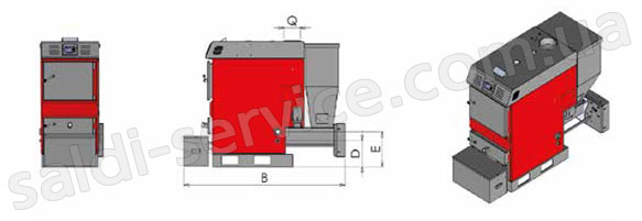
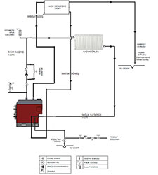
The PEL 20-100 boiler is designed for heating residential and industrial premises, hot water supply systems, wood drying chambers equipped with a continuous heating water heating system with forced circulation and other technological purposes.
Model PEL 20-100 is a solid fuel boiler with mechanized combustion of bulk fuel, in a retort with a lower fuel supply. Fuel is pushed by an auger to a stationary retort. Primary air is supplied under the retort through openings located on the side surfaces of the burner. The retort is cooled by primary air.
To achieve the correct ratio of the costs of supplying primary and secondary air is regulated separately. Bulk fuel is: wood waste — granulated sawdust and shavings, granular waste from production — sunflower husks and buckwheat.
Granulated fuel fraction 8x40 mm. The design of the boiler provides for the automatic removal of ash and unburned residues beyond the boiler furnace volume into a separate ash container. The ash conveyor has independent separate drives, with switching on from the boiler controller. The boiler is equipped with an automatic fuel ignition system, which simplifies operation and allows operating a cascade of several boilers — in automatic mode. Exhaust flue gases from the furnace passing through a two-way tube bundle and a chimney adapter give heat to the coolant. The boiler is made of plate steel, insulated with basalt insulation and coated with sheet metal with a polymer coating. Automation of the boiler provides optimal conditions for the combustion of fuel, modulation of power within 20-100%, emergency and fire alarms.
| Model | PEL-20 | PEL-25 | PEL-40 | PEL-60 | PEL-80 | PEL-100 |
|---|---|---|---|---|---|---|
| Power, kW | 23 | 29 | 46 | 69 | 93 | 116 |
| Consumption, kcal | 20000 | 25000 | 40000 | 60000 | 80000 | 100000 |
| Overall dimensions, WxDxH, m | 0,7x1,55x1,3 | 0,7x1,55x1,4 | 0,65x1,5x1,55 | 0,8x1,75x1,45 | 0,8x1,75x1,5 | 0,8x1,8x1,6 |
| D, mm | 420 | 420 | 420 | 300 | 350 | 350 |
| F, mm | 420 | 420 | 420 | 400 | 450 | 450 |
| Diameter of the chimney (Q), mm | 140 | 140 | 140 | 200 | 200 | 200 |
| Supply/return pipe, inch | 1 | 1 | 1 | 1/2 | 2 | 2 |
| Branch pipe for installation of safety group, inch | 1 | 1 | 1 | 1 | 1 | 1 |
| Drain pipe, inch | 1/2 | 1/2 | 1/2 | 1/2 | 1/2 | 1/2 |
| Water capacity, l | 70 | 90 | 110 | 135 | 165 | 210 |
| Fuel hopper capacity, l | 100 | 130 | 140 | 140 | 175 | 205 |
| Working pressure, bar | 3 | 3 | 3 | 3 | 3 | 3 |
| Test pressure, bar | 4,3 | 4,3 | 4,3 | 4,3 | 4,3 | 4,3 |
| Temperature control, °C | 35-85 | 35-85 | 35-85 | 35-85 | 35-85 | 35-85 |
| Max. working temperature, °C | 90 | 90 | 90 | 90 | 90 | 90 |
| Gear, W | 180 | 180 | 180 | 180 | 180 | 180 |
| Fan watts | 105 | 105 | 105 | 105 | 240 | 240 |
| Ash hopper capacity, l | 50 | 50 | 50 | 50 | 50 | 50 |
| Frequency of current and voltage, V/Hz | 230/50 | 230/50 | 230/50 | 230/50 | 230/50 | 230/50 |
| Working current, A | 16 | 16 | 16 | 16 | 18 | 18 |